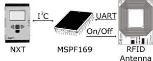
 Inspired by Sivan Toledo’s IR-remote I decided to make an RFID reader for the NXT. An RFID tag is an object that wirelessly can be identified using radio waves. The most common RFID tags are ID-cards or tokens. As show on the block diagram the RFID reader uses a microcontroller (MCU) and an RFID antenna. The NXT communicates with the MCU through the I2C protocol while the microcontroller itself reads the data from the RFID antenna using an UART bus. The RFID antenna I used is from Parallax and is designed to read passive RFID tags. At the Parallax website you will also find compatible tokens and cards. I used an MSP430F169 MCU from Texas Instruments. This MCU might be overkill but I chose the MSP430F169 based on the following considerations. First of all the MSU has both an UART and an I2C interface which was what I needed. Second of all the MCU has a lot of memory to store RFID tag data. Also I have already worked with the MSP430x1xx series and therefore didn’t have to spend time learning how to program a new MCU family.
Each RFID tag has a unique 10 byte ID which is read when moving the tag within range of the RFID antenna. The MCU reads the data from the antenna and if a RFID tag is read the tag is compared with the stored RFID tags. If a match is found the RFID tag can be read as a single byte by the NXT. If a match is not found the NXT will read an empty byte. The NXT can also check if the MCU has read a new RFID tag since the larst tag was read. To save power the NXT can turn the RFID antenna on and off by sending a command to MCU. In the video above you will see a demonstration of an NXC program that reads three different RFID cards – two of the cards are accepted while the last is rejected. Use the download link to view the NXC source that was used in the video. Below you will also find more details on how the NXT RFID reader works and how it is constructed.
Pictures
-
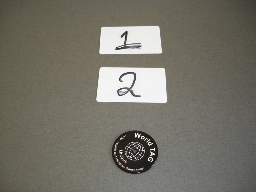
- RFID cards and tags
-
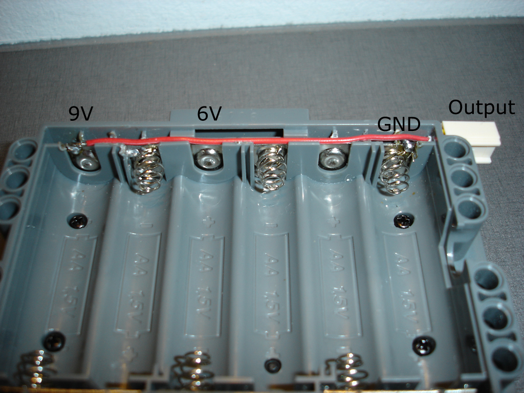
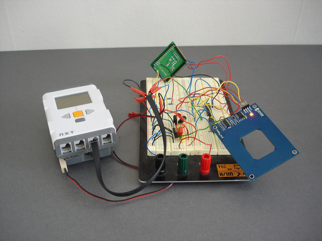
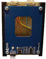
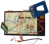
- In the test circuit I powered the sensor from the NXT batteries
-
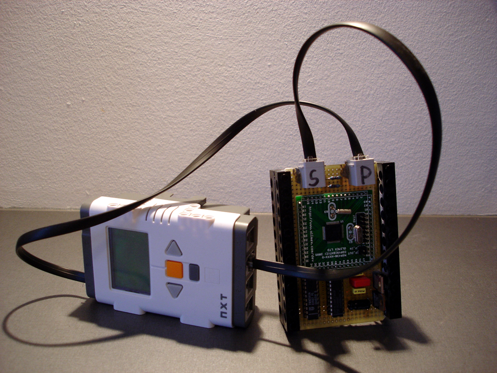
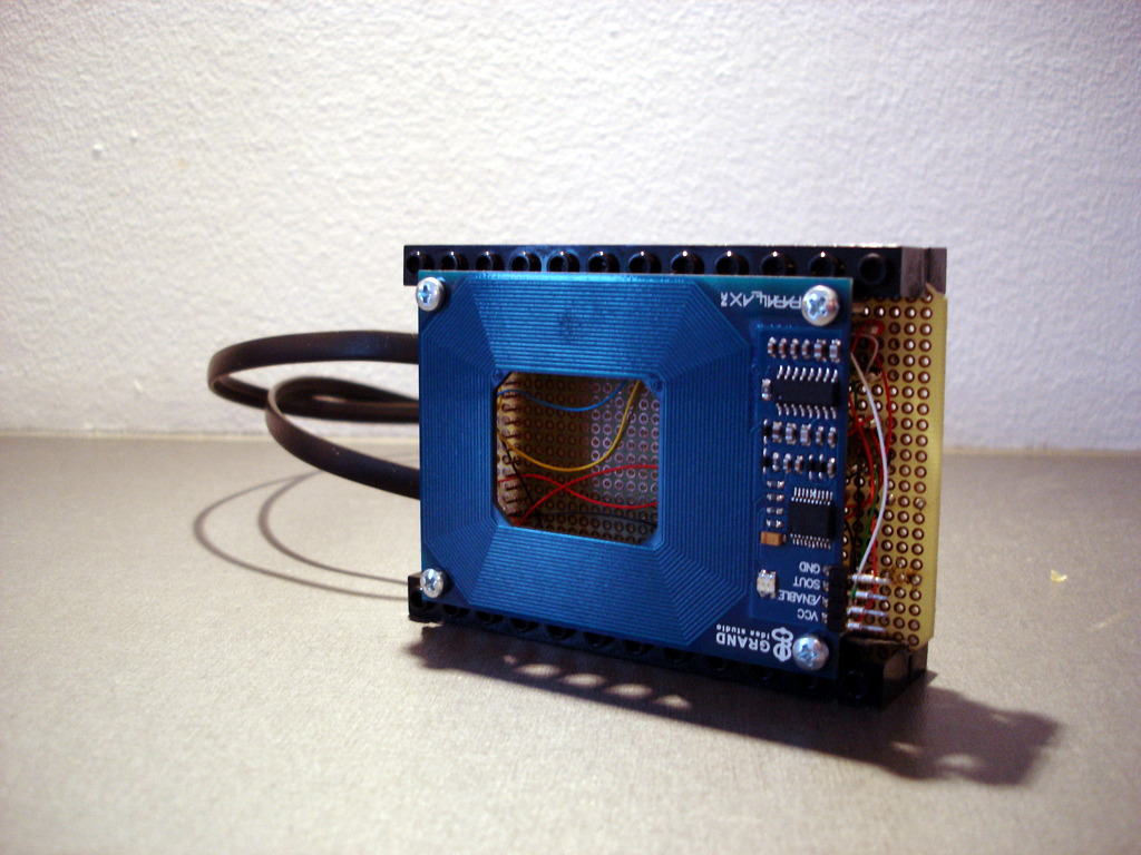
- Here the RFID reader is powered from the motor port
Circuit
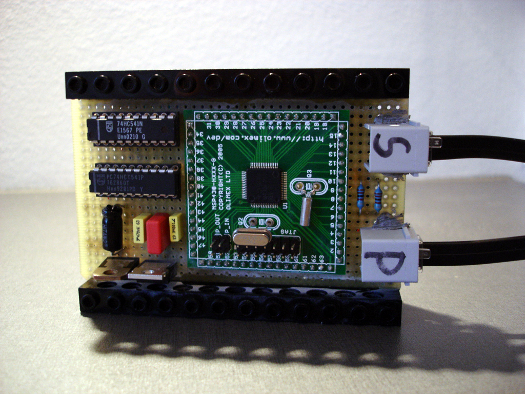
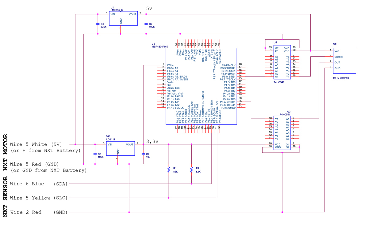
The RFID antenna runs at 5V and uses 100mA when it is on and ready to read. The sensor port of the NXT can only deliver 180mA at 4.3 or 16mA at 8.2V – so either the voltage is to low or there isn’t enough juice. The easy way to solve this is to power the sensor from a motor port or directly from the NXT batteries – in case you need all three motors. The microcontroller runs at 1.8 to 3.6 volts. To get the voltages I needed I used a 3.3V regulator for the MCU and a 5V regulator for the RFID antenna. Since the MCU and the antenna run at different voltages I used a 74HC541 line driver to converts the 5V output from the antenna to a 3.3V input-signal to the MCU. In the same manner the MCU’s 3.3V output-signal is converted to 5V.
Programming the MCU
The program for the MCU has two objectives. The MCU must read data from the RFID antenna and compare it with a stored tag and at the same time communicate with the NXT. The program is written in C using Texas Instruments free programming environment IAR Kickstart. When moving an RFID tag within range of the RFID antenna the tag is read over and over and thereby creating a byte-stream. The 10 bytes in the RFID tag are separated by a start and stop byte as shown on the image below.

Each byte from the antenna causes an interrupt to be called on the MCU. The interrupt stores each byte in an input-buffer. Within the main program the MCU reads any new bytes from the input buffer and analyzes the byte-stream looking for RFID tags. When a RFID tag has been read it is compared with the stored tags and the NXT can now read the RFID tag as a single byte. Finding RFID tags from the antenna byte-stream and the comparison are done with a state machine. The state machine is shown below. Click on the image to enlarge.

Communicating with the NXT
The NXT can communicate with the RFID reader by sending I2C commands to the MCU. The NXT can send five commands. Each command contains two bytes. The first byte (byte 0) is the 7-bit I2C address + an R/W bit. Byte 1 is the byte that tells the RFID reader which action to perform. In the table below the five commands are listed.
| Command | Byte 0 | Byte 1 | Action | Reply when read bit is set |
| RFID_ON | Adress + R/W bit | 0x01 | Turns on the RFID antenna | Returns one byte with the state of the RFID antenna (On/Off) |
| RFIED_OFF | Adress + R/W bit | 0x02 | Turns off the RFID antenna | Returns one byte with the state of the RFID antenna (On/Off) |
| STATE | Adress + R/W bit | 0x03 | none | Returns one byte with the state of the RFID antenna (On/Off) |
| NEW_RFID_TAG | Adress + R/W bit | 0x04 | none | Returns one byte. Returns 1 if a new RFID tag has been read otherwise 0 |
| GET_RFID_TAG | Adress + R/W bit | 0x05 | none | Returns one byte with the RFID tag. The byte represents the ID of the RFID tag stored in the MCU. If no match is found it will return 0. |
When the tag is read using GET_RFID_TAG the NEW_RFID_TAG command will return 0 untill the MCU has detected a new RFID tag.
Follow